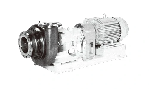
ULP ULP18.5 (150 mm × 100 mm) Process Pumps
EBARA ULP 18.5 pulp pump special design, including pulp pump maintainability, easy adjustment of the gap on the front side of the impeller to shorten the maintenance time, functional labyrinth seal to block the leakage of bearing oil, diversified shaft seal, service system connecting national services, durable side protection plate to prevent wear of the pump casing, 150 × 100 Pulp Pump. ULP 18.5 main engine and impeller are made of special cast iron to increase wear resistance.
In the detailed model, ULP represents the model, 4 represents the number of poles 4 to 6, 5 represents the frequency of 50 Hz, 18.5 represents the motor power of 18.5 kW, and 150 × 100 represents the inlet and outlet diameters.
As part of EMAC, PumpMac provides abundant premium pump-driven power pack options, WPT PTO, Advance gearbox and pump head, as well as customized water pump set. We also have a set of NFPA20 standard engine power pack accessories including air intake shut-off valve, DC contactor, engine control panel, jacket water heater etc.
We provide full life cycle services for all customers, from design to power system supply, from installation to commissioning, from after-sales service training to spare parts supply, from trouble shooting to overhaul technical support.
Advantages of ULP ULP18.5 (150 mm × 100 mm) Process Pumps
The clearance between the impeller and the front protection plate of the clearance adjustment mechanism can be adjusted from the outside without disassembling the pump, so the time for replacing the impeller can be relatively short.
Labyrinth seal The lubricating oil is sealed by a non-contact labyrinth seal with the main shaft, which can prevent oil leakage from the bearing without wearing the main shaft.
Diversity of shaft seals The seal chamber is separated from the pump casing, making it easy to handle various mechanical seals.
The three-part pump casing structure allows for easy disassembly and assembly of the pump without removing the outlet pipe from the pump casing, significantly reducing maintenance time.
The unique hydraulic design of the impeller enables the pump to perform at a high efficiency and promote the reduction of operating costs.
Technical Specifications
| Working medium: | 0.3-5% pulp liquid (up to 6%) |
| Temperature: | 0-95℃ |
| Installation location: | Indoor and outdoor |
| Material/Pump Sales: | FC200/SCS13 |
| Material/Impeller: | HT250/SCS13 |
| Material/Spindle: | SUS304 |
| Material/Bushing: | SUS304 |
| Structure/Shaft seal: | Packing seal – non-water cooling |
| Structure/Flushing method: | External flushing |
| Structure/Bearings: | Ball bearings – non-water cooled |
| Structure/Impeller: | Fully open |
| Flangespecifications/Inhalation/Press out: | JIS 10K FF |
| Water flowdirection/Inhalation/Press out: | level/Top vertical |
Water Pump Model | Water Pump Diameter | Motor Poles | Synchronous Speed | Motor Power | Frequency |
| ULP2.2 | 125mm × 100mm | 4-6 | 1500min-1 | 2.2 kW | 50 hz |
| ULP3.7 | 125mm × 100mm | 4-6 | 1500min-1 | 4 kW | 50 hz |
| ULP5.5 | 125mm × 100mm | 4-6 | 1500min-1 | 5.5 kW | 50 hz |
| ULP7.5 | 125mm × 100mm | 4-6 | 1500min-1 | 7.5 kW | 50 hz |
| ULP11 | 125mm × 100mm | 4-6 | 1500min-1 | 11 kW | 50 hz |
| ULP15 | 125mm × 100mm | 4-6 | 1500min-1 | 15 kW | 50 hz |
| ULP18.5 | 125mm × 100mm | 4-6 | 1500min-1 | 18.5 kW | 50 hz |
| ULP15 | 150mm × 100mm | 4-6 | 1500min-1 | 15 kW | 50 hz |
| ULP18.5 | 150mm × 100mm | 4-6 | 1500min-1 | 18.5 kW | 50 hz |
| ULP22 | 150mm × 100mm | 4-6 | 1500min-1 | 22 kW | 50 hz |
| ULP30 | 150mm × 100mm | 4-6 | 1500min-1 | 30 kW | 50 hz |
| ULP37 | 150mm × 100mm | 4-6 | 1500min-1 | 37 kW | 50 hz |
| ULP5.5 | 150mm × 125mm | 4-6 | 1500min-1 | 5.5 kW | 50 hz |
| ULP7.5 | 150mm × 125mm | 4-6 | 1500min-1 | 7.5 kW | 50 hz |
| ULP11 | 150mm × 125mm | 4-6 | 1500min-1 | 11 kW | 50 hz |
| ULP15 | 150mm × 125mm | 4-6 | 1500min-1 | 15 kW | 50 hz |
| ULP11 | 200mm × 150mm | 4-6 | 1500min-1 | 11 kW | 50 hz |
| ULP15 | 200mm × 150mm | 4-6 | 1500min-1 | 15 kW | 50 hz |
| ULP18.5 | 200mm × 150mm | 4-6 | 1500min-1 | 18.5 kW | 50 hz |
| ULP22 | 200mm × 150mm | 4-6 | 1500min-1 | 22 kW | 50 hz |
| ULP30 | 200mm × 150mm | 4-6 | 1500min-1 | 30 kW | 50 hz |
| ULP37 | 200mm × 150mm | 4-6 | 1500min-1 | 37 kW | 50 hz |
| ULP45 | 200mm × 150mm | 4-6 | 1500min-1 | 45 kW | 50 hz |
| ULP55 | 200mm × 150mm | 4-6 | 1500min-1 | 55 kW | 50 hz |
| ULP75 | 200mm × 150mm | 4-6 | 1500min-1 | 75 kW | 50 hz |
| ULP30 | 200mm × 200mm | 4-6 | 1500min-1 | 30 kW | 50 hz |
| ULP37 | 200mm × 200mm | 4-6 | 1500min-1 | 37 kW | 50 hz |
| ULP45 | 200mm × 200mm | 4-6 | 1500min-1 | 45 kW | 50 hz |
| ULP55 | 200mm × 200mm | 4-6 | 1500min-1 | 55 kW | 50 hz |
| ULP75 | 200mm × 200mm | 4-6 | 1500min-1 | 75 kW | 50 hz |
| ULP30 | 250mm × 200mm | 4-6 | 1500min-1 | 30 kW | 50 hz |
| ULP37 | 250mm × 200mm | 4-6 | 1500min-1 | 37 kW | 50 hz |
| ULP45 | 250mm × 200mm | 4-6 | 1500min-1 | 45 kW | 50 hz |
| ULP55 | 250mm × 200mm | 4-6 | 1500min-1 | 55 kW | 50 hz |
| ULP75 | 250mm × 200mm | 4-6 | 1500min-1 | 75 kW | 50 hz |
| ULP90 | 250mm × 200mm | 4-6 | 1500min-1 | 90 kW | 50 hz |
| ULP110 | 250mm × 200mm | 4-6 | 1500min-1 | 110 kW | 50 hz |
| ULP132 | 250mm × 200mm | 4-6 | 1500min-1 | 132 kW | 50 hz |
| ULP160 | 250mm × 200mm | 4-6 | 1500min-1 | 160 kW | 50 hz |
| ——END—— | |||||

| Part Number | Part Name | Material | Remark | quantity |
| 001 | Outlet flange | HT250 | 1 | |
| 008 | Stuffing box | HT250 | 1 | |
| 012 | Inlet flange | HT250 | 1 | |
| 021 | impeller | SCSI 3 | 1 | |
| 031 | Spindle | SUS304 | 1 | |
| 039-1 | key | S50C | 1 | |
| 039-2 | key | SUS316 | 1 | |
| 041 | axis set | SUS304 | 1 | |
| 048 | Impeller lock nut | SUS316 | 1 | |
| 051 | Bearing bracket | HT250 | 1 | |
| 053-1 | Bearing gland | HT250 | 1 | |
| 053-2 | Bearing gland | HT250 | 1 | |
| 053-5 | Bearing gland | HT250 | 1 | |
| 056-1 | axis Cheng | NSK | 1 | |
| 056-2 | Bearings | NSK | 1 | |
| 071-1 | Rear pump housing | SCS13 | 1 | |
| 071-2 | Front pump housing | SCSI 3 | 1 | |
| 090 | Water Ring | SUS316 | 1 | |
| 091 | Packing gland | SCS14 | 1 | |
| 093-3 | Gland | CAC406 | 1 | |
| 115-15 | O Type ring | NBR | 1 | |
| 115-18 | O Type ring | EPDM | 1 | |
| 115-3 | O Type | EPDM | 1 | |
| 115-4 | O Type | EPDM | 1 | |
| 115-7 | O Type | NBR | 1 | |
| 117-6 | Gasket | 1 | ||
| 117-7 | Gasket | 1 | ||
| 119 | filler | P#6501L | 6 | |
| 120-1 | bolt | SS400 | 1 group | |
| 120-16 | bolt | SS400 | 4 | |
| 120-17 | bolt | SS400 | 4 | |
| 120-18 | Impeller lock nut bolt | SUS316 | 1 | |
| 120-3 | bolt | SS400 | 4 | |
| 120-38 | bolt | SS400 | 4 | |
| 120-8 | bolt | SUS403 | 6 | |
| 120-9 | bolt | SS400 | 6 | |
| 124 | Packing gland bolts | SUS316 | 2 | |
| 129 | Bearing locating ring | SS400 | 1 | |
| 136 | Bearing sleeves | SS400 | 1 | |
| 255 | Oil level gauge | 1 | ||
| 285 | Exhaust valve | Plastic material | 1 |
Safety Instructions and Preventive Maintenance Guide
Requirements for use
Pumps play a significant role in a variety of industries and applications, ensuring the smooth movement of liquids and gases. However, in order to maintain top performance and safety, it is essential to adhere to routine maintenance procedures and safety recommendations. This guide aims at providing the detailed information about pump safety and preventive maintenance.
Safety Instructions
1. Read the Manual
Before using EBara pumps, read and understand the handbook thoroughly. Make sure you understand the pump’s specifications, capabilities, and safety precautions.
2. Proper Installation
Ensure the pump is put appropriately according to the guidelines. Improper installation can cause operating inefficiencies and safety issues.
3. Ventilation
Operate pumps in well-ventilated areas to prevent the buildup of potentially harmful gases or vapors. If working in confined spaces, use proper ventilation equipment.
4. Emergency Shutdown Procedures
Familiarize yourself with emergency shutdown procedures in case of malfunction, leakage, or any other hazardous situation. Ensure all personnel know how to operate emergency shutdown mechanisms.
5. Regular Inspections
Conduct routine inspections of the pump and its components for signs of wear, damage, or leaks. Address any issues promptly to prevent accidents or system failures.
6. Chemical Compatibility
If handling hazardous chemicals, ensure the pump materials are compatible with the fluid being pumped or refer our chemical compatibility chart for more information. Incompatible materials can lead to corrosion, leaks, or chemical reactions.
Preventive Maintenance
1. Regular Lubrication
Keep bearings, seals, and other moving parts properly lubricated. Insufficient lubrication can lead to premature wear and breakdowns.
2. Inspect Seals and Gaskets
Check seals and gaskets for wear, damage, or leaks regularly. Replace any worn or damaged seals to prevent fluid leakage and maintain pump efficiency.
3. Check Motor Alignment
Ensure the pump motor is properly aligned with the pump shaft to prevent excessive wear on bearings and seals. Misalignment can lead to premature failure and costly repairs.
4. Replace Worn Parts
Keep an inventory of spare parts and replace worn or damaged components as needed. Regularly check wear parts such as impellers, seals, and bearings for signs of deterioration.
5. Schedule Maintenance
Develop a preventive maintenance schedule based on manufacturer recommendations and operating conditions. Regular maintenance helps prevent unexpected breakdowns and extends the life of the pump.
6. Document Maintenance Records
Keep detailed records of all maintenance activities, including inspections, repairs, and replacements. This information helps track the pump’s performance over time and identify any recurring issues.
By following these safety instructions and preventive maintenance practices, you can ensure the safe operation and longevity of your pumps while minimizing the risk of accidents or downtime. Remember, prioritizing safety and proactive maintenance is key to maximizing pump efficiency and reliability.
Note: All Above Data are Just for Reference, All Data Might Change Without Notices or Updates, Please Contact Our Sales Team to Confirm All Details Via WhatsApp or Email.

Engine Sale Manual

Installation Drawing

Installation Manual

Operation Manual

Parts Catalogue